Solved thermodynamics exercise

Rectangular refrigeration cycle

Exercise 15 · Lesson 5Application to the Ideal Gas

  • thermodynamic cycle
  • rectangular cycle
  • Clapeyron diagram
  • work
  • heat
  • area
  • ideal gas
  • refrigeration cycle
  • refrigerator
  • COP

Statement

Consider nn moles of a monatomic ideal gas, with U=32nRTU=\frac{3}{2}nRT, traversing quasi-statically the counterclockwise rectangular cycle

A(P1,V1)B(P1,V2)C(P2,V2)D(P2,V1)A,A(P_1,V_1)\to B(P_1,V_2)\to C(P_2,V_2) \to D(P_2,V_1)\to A,

where V2>V1V_2>V_1 and P2>P1P_2>P_1. We write

ΔP=P2P1>0,ΔV=V2V1>0.\Delta P=P_2-P_1>0, \qquad \Delta V=V_2-V_1>0.

This refrigeration cycle is used as a model of a refrigerator. Its refrigeration coefficient of performance (COP) is defined by

COP=QfWin=QfWcycle,\mathrm{COP}=\frac{Q_f}{W_{\mathrm{in}}} =\frac{Q_f}{W_{\mathrm{cycle}}},

where Qf>0Q_f>0 is the total heat extracted by the gas along the branches where it receives heat, and Wcycle>0W_{\mathrm{cycle}}>0 is the net work it receives.

  1. Plot the cycle in the Clapeyron diagram (P,V)(P,V) and specify the nature of each branch.
  2. Calculate the work received along each of the four branches in terms of ΔV\Delta V when it varies, then the total work in terms of ΔP\Delta P and ΔV\Delta V. Recover its value from the area of the rectangle.
  3. Express ΔU\Delta U and QQ along each branch in terms of P1P_1, P2P_2, V1V_1, V2V_2, ΔP\Delta P, and ΔV\Delta V, using ΔP\Delta P for the isochores and ΔV\Delta V for the isobars.
  4. Verify that ΔUcycle=0\Delta U_{\mathrm{cycle}}=0 and Qcycle=WcycleQ_{\mathrm{cycle}}=-W_{\mathrm{cycle}}. Is the cycle a power or refrigeration cycle? Along which branches does the gas receive heat, and along which does it release heat? Interpret these exchanges by identifying the cold and hot reservoirs: what is being cooled here?
  5. Deduce the refrigeration COP of the cycle in terms of P1P_1, P2P_2, V1V_1, and V2V_2.
  6. Interpret the COP physically. Why can it be greater than 1, unlike the efficiency of a heat engine?
  7. Numerical application: P1=1,0P_1=1{,}0 bar, P2=3,0P_2=3{,}0 bar, V1=5,0V_1=5{,}0 L, and V2=15,0V_2=15{,}0 L. Give WW and QQ along each branch, then their balances over the cycle and the COP.

Hint

Hint
Along an isochore, nRΔT=VΔPnR\,\Delta T=V\,\Delta P and the work is zero. Along an isobar, nRΔT=PΔVnR\,\Delta T=P\,\Delta V and W=PΔVW=-P\Delta V. Every state function returns to its initial value at the end of a cycle.

Detailed solution

Solution
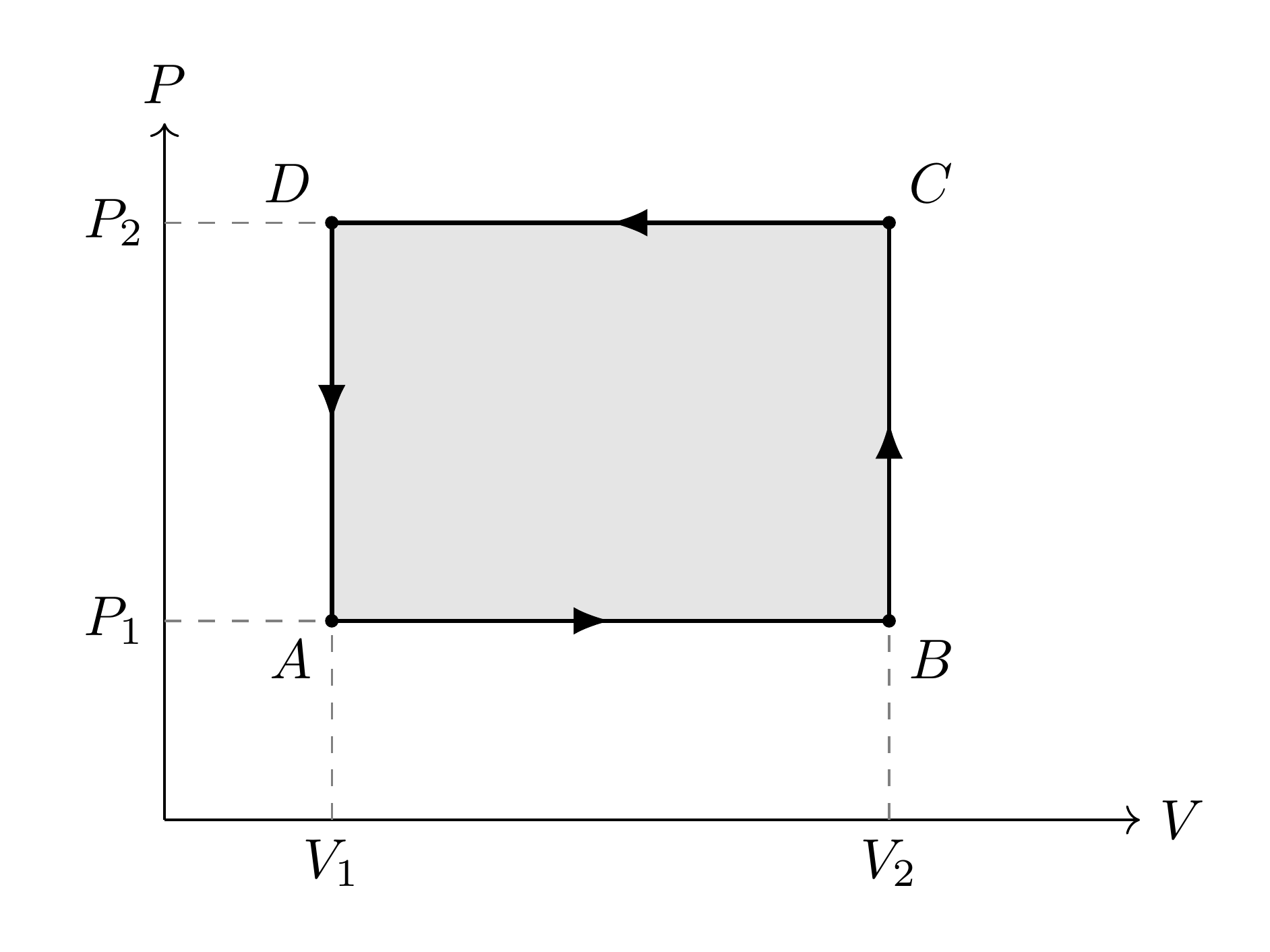
Question 1. Points AA, BB, CC, and DD are at the bottom left, bottom right, top right, and top left, respectively. Branches ABA\to B and CDC\to D are isobaric; BCB\to C and DAD\to A are isochoric. The path ABCDAA\to B\to C\to D\to A is counterclockwise.

The rectangular isobaric—isochoric cycle in the Clapeyron diagram.
Figure 1. The rectangular isobaric—isochoric cycle in the Clapeyron diagram.

Question 2. The work received by the gas is

W=PextdV.W=-\int P_{\mathrm{ext}}\,\mathrm dV.

It is zero along the isochores BCB\to C and DAD\to A. Along the two isobars,

WAB=P1(V2V1)=P1ΔV,WCD=P2(V1V2)=P2ΔV.W_{AB}=-P_1(V_2-V_1)=-P_1\Delta V, \qquad W_{CD}=-P_2(V_1-V_2)=P_2\Delta V.

Thus,

Wcycle=(P1+P2)ΔV=ΔPΔV>0.\boxed{W_{\mathrm{cycle}} =(-P_1+P_2)\Delta V =\Delta P\,\Delta V>0}.

This value is indeed the area of the rectangle in the Clapeyron diagram.

Question 3. For the monatomic ideal gas,

ΔU=ncVΔT=32nRΔT.\Delta U=nc_V\Delta T=\frac32nR\Delta T.

Along an isobar, the equation of state gives nRΔT=PΔVbranchenR\Delta T=P\Delta V_{\mathrm{branche}}. Consequently,

ΔUAB=32P1ΔV,ΔUCD=32P2ΔV.\Delta U_{AB}=\frac32P_1\Delta V, \qquad \Delta U_{CD}=-\frac32P_2\Delta V.

Along an isochore, it gives nRΔT=VΔPbranchenR\Delta T=V\Delta P_{\mathrm{branche}}, hence

ΔUBC=32V2ΔP,ΔUDA=32V1ΔP.\Delta U_{BC}=\frac32V_2\Delta P, \qquad \Delta U_{DA}=-\frac32V_1\Delta P.

Finally, the first law ΔU=Q+W\Delta U=Q+W, that is, Q=ΔUWQ=\Delta U-W, gives the summary table:

BranchWΔUQ=ΔUWABP1ΔV32P1ΔV52P1ΔVBC032V2ΔP32V2ΔPCDP2ΔV32P2ΔV52P2ΔVDA032V1ΔP32V1ΔP\begin{aligned} \begin{array}{c|c|c|c} \text{Branch} & W & \Delta U & Q=\Delta U-W\\ \hline A\to B & -P_1\Delta V & \frac32P_1\Delta V & \frac52P_1\Delta V\\[2pt] B\to C & 0 & \frac32V_2\Delta P & \frac32V_2\Delta P\\[2pt] C\to D & P_2\Delta V & -\frac32P_2\Delta V & -\frac52P_2\Delta V\\[2pt] D\to A & 0 & -\frac32V_1\Delta P & -\frac32V_1\Delta P \end{array} \end{aligned}

Question 4. The sum of the changes in internal energy is zero. The first law therefore requires

Qcycle=Wcycle=ΔPΔV<0.Q_{\mathrm{cycle}}=-W_{\mathrm{cycle}}=-\Delta P\,\Delta V<0.

Overall, the gas receives work: this is a refrigeration cycle. It receives heat along ABA\to B and BCB\to C. Along these two branches, it extracts heat from the cold reservoirs with which it is placed in contact: it is therefore these external reservoirs (for example, the compartment and food in a refrigerator), rather than the working gas itself, that are cooled.

Along CDC\to D and DAD\to A, by contrast, the gas releases heat to the hot reservoirs, for example the air in the room. Denoting by Qchaud>0Q_{\mathrm{chaud}}>0 the total heat received by these reservoirs,

Qchaud=(QCD+QDA)=52P2ΔV+32V1ΔP.Q_{\mathrm{chaud}} =-(Q_{CD}+Q_{DA}) =\frac52P_2\Delta V+\frac32V_1\Delta P.

The cycle thus transfers heat from the cold reservoirs to the hot reservoirs by means of the work it receives.

Question 5. The heat extracted by the gas is

Qf=QAB+QBC=52P1ΔV+32V2ΔP.Q_f =Q_{AB}+Q_{BC} =\frac52P_1\Delta V+\frac32V_2\Delta P.

It follows that

COP=52P1ΔV+32V2ΔPΔPΔV.\boxed{ \mathrm{COP} =\frac{\frac52P_1\Delta V+\frac32V_2\Delta P} {\Delta P\,\Delta V}. }

Question 6. The COP measures the refrigeration benefit obtained relative to the work input: a COP equal to kk means that each joule of work supplied allows kk joules of heat to be extracted from the cold reservoirs.

Unlike the efficiency of a heat engine, the COP is not the fraction of received energy that is converted into work. The gas receives both the work WinW_{\mathrm{in}} and the heat QfQ_f extracted from the cold reservoirs, then rejects their sum to the hot reservoirs:

Qchaud=Qf+Win.\boxed{Q_{\mathrm{chaud}}=Q_f+W_{\mathrm{in}}}.

There is therefore no reason for QfQ_f to be less than WinW_{\mathrm{in}}, and the COP can readily be greater than 1 without violating energy conservation.

Question 7. Here ΔP=2,0×10⁵\Delta P=2{,}0\times10^5 Pa and ΔV=1,0×10²\Delta V=1{,}0\times10^{-2} m3^3:

BranchW (J)ΔU (J)Q (J)AB100015002500BC045004500CD300045007500DA015001500\begin{aligned} \begin{array}{c|r|r|r} \text{Branch} & W\ (\mathrm J) & \Delta U\ (\mathrm J) & Q\ (\mathrm J)\\ \hline A\to B & -1000 & 1500 & 2500\\ B\to C & 0 & 4500 & 4500\\ C\to D & 3000 & -4500 & -7500\\ D\to A & 0 & -1500 & -1500 \end{array} \end{aligned}

Thus Wcycle=+2000W_{\mathrm{cycle}}=+2000 J, Qcycle=2000Q_{\mathrm{cycle}}=-2000 J, and ΔUcycle=0\Delta U_{\mathrm{cycle}}=0. The heat extracted is

Qf=2500+4500=7000 J,Q_f=2500+4500=7000\ \mathrm{J},

whereas the heat released to the hot reservoirs is

Qchaud=7500+1500=9000 J=Qf+Wcycle.Q_{\mathrm{chaud}}=7500+1500=9000\ \mathrm{J} =Q_f+W_{\mathrm{cycle}}.

The refrigeration coefficient of performance is therefore
COP=70002000=3,5.\mathrm{COP}=\frac{7000}{2000}=3{,}5.